
Hi guys. Today I will post in English because this project was developed with international help and sources.
Pay attention that is not a beginner project. There is a lot of things that you need know before start to think build one. It is mandatory understand digital chips, how to program, AVR platforms etc.
This project uses one Attiny84A and is based on Harold Sabrotone Tap Tempo idea (thank you brother), but with a different code, functions and perspectives.
In resume, this is a Tremolo pedal with a tap tempo function. I used a 20 step rotary encoder.
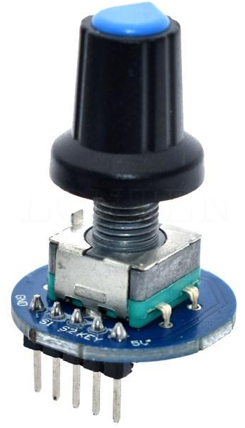
The push switch on encoder change the functions:
Speed
Wave Form
Multiplier
Depth
To understand what function is active, a RGB led indicates each one.
Blue – Speed
Green – Wave Form
Red – Multiplier
Pink – Depth
For now I put 7 wave form possibilities in the code:
Random
Sine
Tremcopter
Square
Triangle
Ramp down
Ramp up
Measuring with a scope we have a visual idea of each waveform:
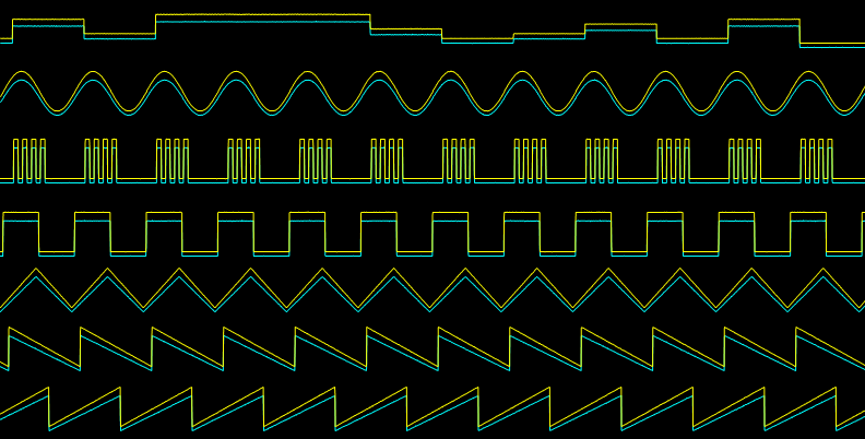
Okay, this is what the digital part does.
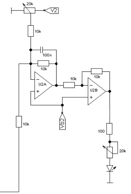
In analog (audio) section, basically it is a Tremulus Lune circuit that uses a LDR controlling the audio, receiving light from led controlled by digital chip. Each pulse makes audio up (led on) and down (led off).

The theory is easy, but the construction not. Each pulse injects a lot of ticking noise in audio signal and is hard to remove it. I tried a lot of solutions that I found on the internet. The worst was a transistor driving a led. You need to try more than 10 transistors and leds to find an acceptable match to deal with noise. My best solution to drive the output led was use one 4558 opamp circuit. This great solution I found in Twin Peaks Harmonic Tremolo project (thank you David Rolo).
This project had three different prototypes. The first I built on Arduino breadboard.

The first version didn´t work great with much noise and contact joints problems. So I changed to a soldered breadboard.

LDR Selection:
I tried different LDR and the most part of them work well, but to sounds great the best range is 5k to 1M (light-dark). You can use LDR that has less than 5k on light, but it injects more “hiss” on the audio. Dark resistance more than 1M needs to use more gain from de ampop and noise going up easier.
I got good results with:
5k-500k (light-dark)
8k-500k (light-dark) – My final choice with 10k Linear pot to gain control.
10k-1M (light-dark)
Led Selection:
I used a low current led 5mm red. No big secrets here. Try to run this led lower as you can to avoid hiss and ticking noises. High bright led has much light to the LDR sensibility. It isn´t an advantage use them. As the led run very low, you need to protect the junction LED/LDR very well to isolates any external light interference. I used an aluminium sheet but you can use thermal tube.
Yes, you can use optocouplers, but honestly for the price, you can make a lot of them at home with same results.
Opamp selection:
At beginning I used one TL072, but when tried one OPA2134A the audio run very silent and helped the circuit to get off all residual noise.
The code:
The code was developed in Atmel Studio 7.0 and burned with an AVR ISP Programmer. This programmers are cheap (3 dollars) and you can also use your Arduino to do it. In my case I bought a Pololu Programmer that includes an Osciloscope very useful to check waveforms and calibrate the led bright to get a consistent output.
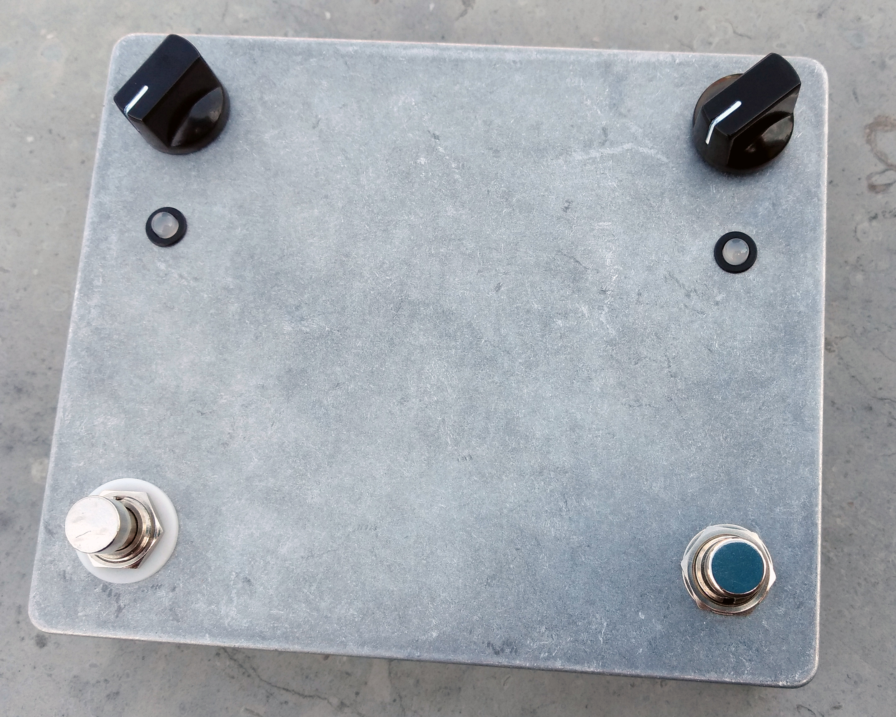
The next step was make a “final” pedal version to use like a normal guitar device and change the code playing in real situations.
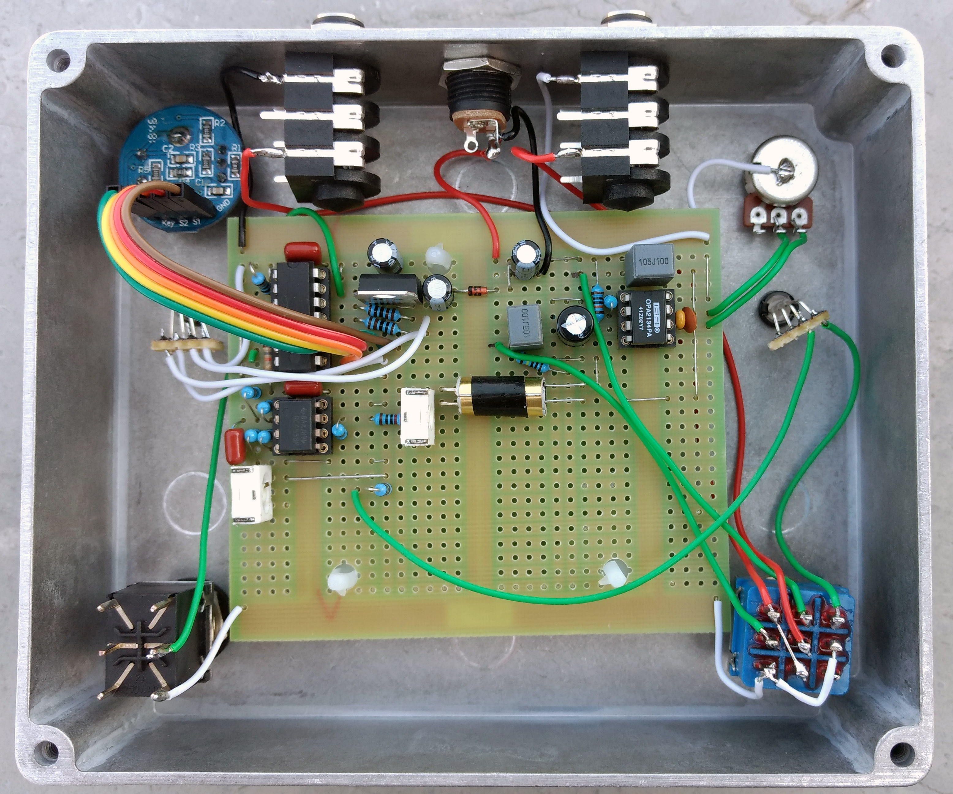
The box that I used is too big, but to run tests and mods is ok. In the future I will create a small PCB layout.
For now I am working to increase waveform options and correcting code bugs. When the code is ok, I will create a final version with professional PCB, but it is to another post.
I recorded this sample video, so enjoy! 😊

Você precisa fazer login para comentar.